| Frederick J. Otto**
Daniel H. Herring**
** Member of ASM International and
member, ASM Heat Treating Society |
Low pressure vacuum carburizing has expanded to encompass
the latest demands of the aerospace, automotive and industrial
markets, particularly in the areas of new material development.
Carburizing techniques have been developed for such advanced
materials as: • Aubert & Duval X13 VDW and XD15NW • Carpenter Technology Corporation Pyrowear 53 and 675 • Bohler Uddeholm N360 Iso Extra, N695, R250, and R350 • Timken CSS-42L, Lescalloy BG42VIM-VAR, CSB-50NIL and CBS-600 • Questek Innovations Ferrium C61, CS62, C69, M60S, and S53 In order to achieve exacting performance requirements, these materials often require custom designed cycles to obtain deep case depths in the range of 0.60 in. - 0.250 in. (1.50 – 6.35 mm). Reduced processing times can be achieved by using high temperature carburizing. Quenching in oil and gas, including gas mixtures, is being used with success. Establishing and controlling critical process parameters are essential, and extensive development work has been done at Midwest Thermal-Vac (MTV) to establish achievable case depths and required temperature uniformity, to create surface carbon control techniques for the avoidance of carbide networks and necklace formation, and to understand thermal characteristics during both heating and cooling when working with parts sensitive to distortion. Why Vacuum Carburizing Is in Demand Only low pressure vacuum carburizing allows the end user to “dial in” settings for case depth, carbon profiles, surface/core hardness, and case/core microstructure, and predict distortion results to achieve required properties at the lowest unit cost. Conventional materials such as 8620, 8822, 9310, and parts that are traditionally atmosphere carburized benefit from these techniques. Documented savings in post-machining operations and material stock allowances make the use of vacuum carburizing practical. An extensive material and process database has been developed by MTV from over 13,000 runs, or an average of 10 carburizing cycles a day using an ECM vacuum carburizing system. Over 1,000 different recipes have been customized using MTV-modified ECM Infracarb software.
Importance of Materials
|
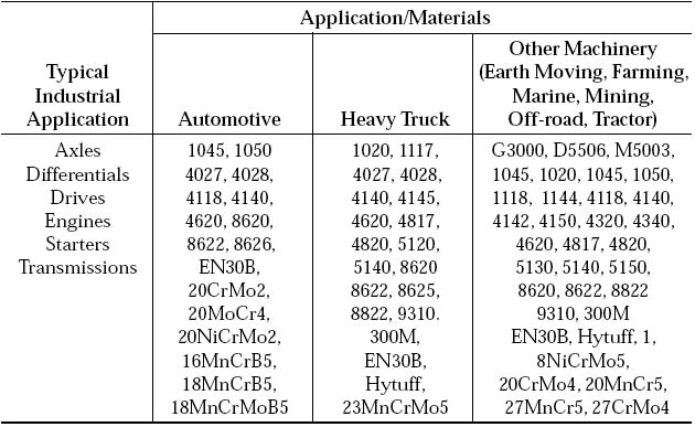
A new generation of materials (Table 2) is emerging to meet today’s service and performance needs. They are designed specifically for high temperature applications, retaining their hardness and mechanical properties well into a service range of 600ºF - 950ºF (315ºC - 510ºC) and higher. Many of these materials are similar in chemistry to that of stainless and tool steels to take advantage of better corrosion and wear resistance with better core microstructures and surface hardness as good as 440C.
 These new materials demand
better control of hardness and carbon
distribution, optimized microstructures,
and control of grain size, retained
austenite, and carbide size.
Extensive work with aerospace
and automotive partners to control
material and microstructure variation
in vacuum carburizing has resulted
in avoidance of many
common problems.
For example, the inherent high chromium content (1 – 17 percent) in these materials makes controlling carbide formation and avoiding carbide networks or necklaces (Fig. 3) a critical issue. Vacuum carburizing (Fig. 4a) means we don’t have to settle for an inferior atmosphere carburized microstructure. Also, no preoxidation or pre-treatment steps are necessary as in atmosphere carburizing due to proprietary surface activation methods.
Table 1 — Conventional Gear Materials
| Material | %C | %Mn | %Cr | %Ni | %Mo | %Si | %V | %Co | %Cb | %Al | %Cu |
|---|---|---|---|---|---|---|---|---|---|---|---|
| XD15NW[a] | 0.37 | — | 15.5 | 0.20 | 1.80 | — | 0.30 | — | — | — | — |
| X13VDW[a] | 0.12 | — | 11.5 | 2.50 | 1.60 | — | 0.03 | — | — | — | — |
| N360 Iso Extra[b] | 0.33 | 0.50 | 15.0 | 0.40 | 1.00 | — | — | — | — | — | — |
| N695[b] | 1.05 | 0.20 | 17.0 | — | 0.50 | 0.50 | — | — | — | — | — |
| R250[b] | 0.83 | 0.70 | 4.00 | — | 4.30 | 0.20 | 1.10 | — | — | — | — |
| R350[b] | 0.14 | 0.30 | 4.25 | 3.50 | 4.30 | 0.18 | — | — | — | — | — |
| CBS-600[c] | 0.19 | 0.60 | 1.45 | — | 1.00 | 1.10 | 0.06 | — | — | 0.06 | — |
| Pyrowear 53[c] | 0.10 | 0.35 | 1.00 | 2.00 | 3.25 | 1.00 | 0.10 | — | — | — | 2.0 |
| Pyrowear 675[c] | 0.07 | 0.65 | 13.0 | 2.60 | 1.80 | 0.40 | 0.60 | — | — | — | — |
| Lescalloy BG42VIM-VAR[d] | 1.15 | 0.50 | 14.5 | — | 4.00 | 0.30 | 1.20 | — | — | — | — |
| CSB-50NIL[d] | 0.13 | 0.25 | 4.20 | 3.40 | 4.25 | 0.20 | 1.20 | — | — | — | — |
| CSS-42L[d] | 0.12 | — | 14.0 | 2.00 | 4.75 | — | 0.60 | 12.5 | 0.02 | — | — |
| Ferrium C61[e] | 0.15 | — | 3.50 | 9.50 | 1.10 | — | 0.09 | 18.0 | — | — | — |
|
Process Parameter Control
Today MTV runs vacuum carburizing loads using temperatures between 1450ºF - 2200ºF (785ºC - 1205ºC). Temperature uniformity, especially in the low temperature ranges, is critical. Amaximum spread of 10ºF is required to maintain tight case depth control throughout the load. This is equally important for vacuum carbonitriding cycles, which can go as low as 1425ºF (775ºC). Effective case depth ranges for vacuum carburized parts routinely vary from 0.010 in. - 0.250 in. (0.25mm - 6.35mm). Amaximum case variation within a load can be held to within 0.005 in. (0.125 mm) and is routinely done so for aerospace and most automotive applications. In one vacuum carbonitriding application the specification called for an extremely shallow case, 0.0005 in.- 0.0025 in., the final part variation achieved was 0.0018 in. - 0.0022in.Surface carbon is controlled in the range of 0.60 - 0.80 percent for most conventional materials, and between 0.45 - 0.75 percent for many of the advanced materials. Controlling retained austenite levels is also important. |
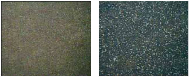 Fig. 3 — Left, Optimized vacuum carburized Pyrowear 675 microstructure. (Mid-Case,
0.090 in. ECD). Right, Non -Optimized atmosphere carburized Pyrowear 675 microstructure
(Mid-Case, 0.065 in. ECD). Fig. 3 — Left, Optimized vacuum carburized Pyrowear 675 microstructure. (Mid-Case,
0.090 in. ECD). Right, Non -Optimized atmosphere carburized Pyrowear 675 microstructure
(Mid-Case, 0.065 in. ECD).
|
 The relationship between carburizing
pressure and gas flow (carrier
and hydrocarbon) as a function of
load surface area has been worked
out to avoid carbide necklaces and
to optimize carbide formation. Pressure
ranges must be allowed to vary
between 3.75 – 15 torr (5 – 20 mbar)
and gas flow, a function of the load
surface area, typically is controlled
between 0.05 – 0.20 cfh (1500 – 6000
ml/hr). Carbon flux is a function of
the type of hydrocarbon gas used.
No preoxidation or pre-treatment
steps are necessary, as they are in atmosphere
carburizing due to proprietary
surface activation methods.
 It has been found that if a temperature variation exists within a load during a preoxidation step, the resultant variation in layer thickness been found to causeresults in non-uniformity of case depth. Finally, oil quenching, and certain combinations of gas type, gas pressure, fan speed, and flow pattern have been found to produce an optimum microstructure of finely dispersed carbides in a matrix of tempered martensite (surface to core). Cross sectional area is an important variable, as is loading configuration.
Application Examples
Whether the need is to deliver
greater horsepower in smaller transmission
packages, survive harsh environments,
stand up to the rigors of
modern warfare or any one of a
number of performance demands,
customers are looking to the new
generation of advanced materials for
the solution. Some typical applications
include:
 Aerospace Sector — The aerospace
industry includes rotorcraft,
aircraft, rocketry, space vehicles and
shuttles, landers and probes. All are
looking to the next generation of
materials in the design of such items
as propulsion systems, landing systems,
control and actuator systems,
stabilizers, exhaust nozzles, wing
sweep actuators, and the like. Many
aerospace clients are working with
us and their steel suppliers to optimize
their designs, manufacturing
methods, and heat treatment
processes. One such application is
in the commercial airline industry
(Fig. 5A) where advanced materials
are used in actuator systems (Fig
5B).
Automotive Sector — Both passenger
car/truck manufacturers and
racing teams rely heavily on vacuum
carburized components for their engine
fuel system, powertrain/transmission,
braking, and steering components.
Most of the major
automotive manufacturers are
working to improve performance by
vacuum heat treatment. One such
application is transmission components,
such as those used by the
racing industry. Fig.5 Actuator bearing.
 Phenomenal race results
(Table 3) have been achieved
using vacuum carburized components
due to increased rear wheel
horsepower with equivalent or reduced
rotating mass.
Industrial Sector — Industrial applications
include heavy duty military
components such as transmission
gears (Fig. 7), hydraulic cams,
valves, seats and bushings, as well
as tools, tool holders, punches, linear
motion machinery, and many others.
These components are typically
made from more conventional
materials.
Unique Application — Vacuum
carburizing has found its way into other challenging applications such as in medical devices, where carburizing
is performed on implant screws (Fig. 8). The addition of carbon
produces a high strength, high hardness surface with excellent wear
and abrasion resistance. Residual compressive stresses at the roots of
the threads are important to help achieve the best fatigue properties.
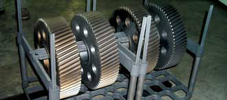

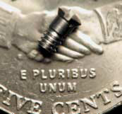 Fig. 8 — Vacuum carburizing of N360 medical
fasteners for implantable devices. (0.10 oz./piece
carburized to 0.0015 in.)
 |
The Future Aerospace and automotive specifications need to be reviewed in light of rapid developments underway with these new materials. Serious consideration must be given to the use of elevated temperature above 1900ºF (1040ºC) carburizing and direct quench to minimize cycle times and reduce carbon absorption without adversely affecting microstructure (Fig. 9, 10). Preoxidation treatments have been found to be unnecessary, and rules for the use of high gas pressure quench-ing need to be better established. Once this is accomplished, vacuum carburizing technology offers almost limitless possibilities. 
|
Fig. 9 — 1600ºF (900ºC) Atmosphere carburized Aubert & Duvall X13VDM |
Fig. 10 — 1950ºF (1065ºC)
Vacuum carburized Pyrowear 675 |
For more information visit our Resources page.
Vacuum Carburizing |
Heat Treat |Plasma
Nitriding | Vacuum
tempering | Directory | Resources
All mtvac.com content is copyright© MtVac2008
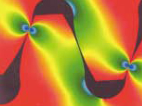 Fig. 1 — Gear stress profile.
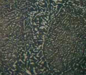 Fig. 2 — Non-optimized Pyrowear 675
microstructure.
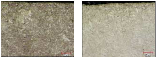 Fig. 5 — Left, Ferrium 69 Gear microstructure (0.040 in. ECD @ 53 HRC). Right, Ferrium
69 Camshaft microstructure (0.100 in. ECD @ 55 HRC)